
Original file (SVG file, nominally 750 × 438 pixels, file size: 34 KB)
Summary
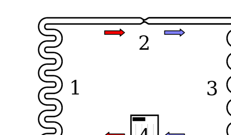
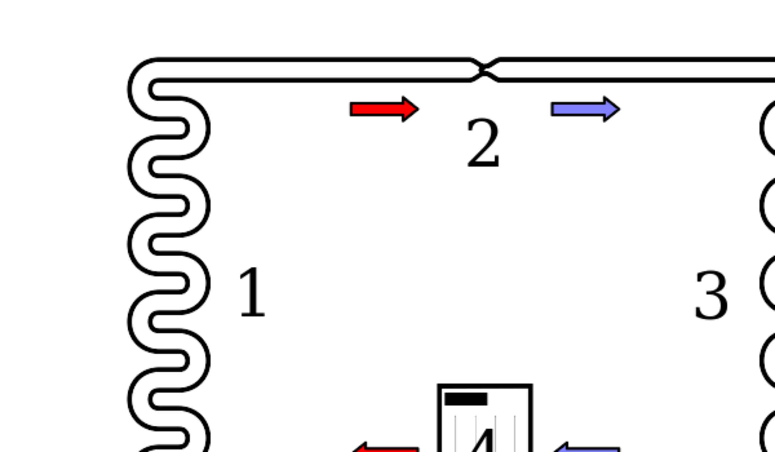
Diagram of a phase change heat pump. Note that the arrows in the diagram are meant to indicate the flow of air and coolant; they do not correspond to heat flow, which in the system depicted is (generally) from right to left. Deutsch: Schema einer Wärmepumpe mit Phasenwechsel. Source Own work Author Ilmari Karonen
Legend Condenser coil (hot side heat exchanger, gas cools and liquifies) Metering Device (liquid expands and cools) Evaporator coil (cold side heat exchanger, liquid vaporizes and heats up) Compressor (gas is compressed and heats up) Red = Gas at high pressure and very high temperature Pink = Liquid at high pressure and high temperature Blue = Liquid at low pressure and very low temperature Light Blue = Gas at low pressure and low temperature
Licensing
| This file is in the public domain, because (no reason given!)
Please verify that the reason given above is valid! Note: if there is a specific licence tag for the reason supplied here, please use it. |
File history
Click on a date/time to view the file as it appeared at that time.
| Date/Time | Thumbnail | Dimensions | User | Comment | |
|---|---|---|---|---|---|
| current | 15:37, 23 October 2023 | | 750 × 438 (34 KB) | Isidore (talk | contribs) | Diagram of a phase change heat pump. Note that the arrows in the diagram are meant to indicate the flow of air and coolant; they do not correspond to heat flow, which in the system depicted is (generally) from right to left. Deutsch: Schema einer Wärmepumpe mit Phasenwechsel. Source Own work Author Ilmari Karonen Legend Condenser coil (hot side heat exchanger, gas cools and liquifies) Metering Device (liquid expands and cools) Evaporator coil (cold side heat exchanger, liquid vaporizes and h... |
You cannot overwrite this file.
File usage
The following page uses this file: