Radiation-patterns-v.png (205 × 405 pixels, file size: 7 KB, MIME type: image/png)
Summary
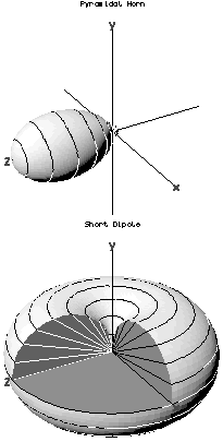
Three-dimensional antenna radiation patterns. The radial distance from the origin in any direction represents the strength of radiation emitted in that direction. The top shows the directive pattern of a horn antenna, the bottom shows the omnidirectional pattern of a simple vertical antenna. James Wlodarczyk (--catslash 23:44, 31 July 2006 (UTC)) - Own work of English Wikipedia user Catslash Example antenna radiation patterns; the first is the computed pattern for a small pyramidal horn (a directional antenna) with boresight on the +z-axis, the second is the computed pattern for a short dipole aligned with the y-axis. The latter pattern is cut-away to show the circular section on the H-plane (horizontal) cut and the figure-of-8 section on E-plane (vertical) cuts. In each pattern, the distance of the surface from the origin is proportional to the magnitude of the E field at some (large) fixed distance from the antenna in the corresponding direction. I.e. Mod[E] (actually Lim r -> ∞ [Mod[E] r]) is plotted radially as a function of direction.
Licensing
| This file is in the public domain, because (no reason given!)
Please verify that the reason given above is valid! Note: if there is a specific licence tag for the reason supplied here, please use it. |
File history
Click on a date/time to view the file as it appeared at that time.
| Date/Time | Thumbnail | Dimensions | User | Comment | |
|---|---|---|---|---|---|
| current | 10:05, 20 July 2023 | | 205 × 405 (7 KB) | Isidore (talk | contribs) | Three-dimensional antenna radiation patterns. The radial distance from the origin in any direction represents the strength of radiation emitted in that direction. The top shows the directive pattern of a horn antenna, the bottom shows the omnidirectional pattern of a simple vertical antenna. James Wlodarczyk (--catslash 23:44, 31 July 2006 (UTC)) - Own work of English Wikipedia user Catslash Example antenna radiation patterns; the first is the computed pattern for a small pyramidal horn (a di... |
You cannot overwrite this file.
File usage
The following page uses this file: